Project results
Publications: 1.R. Nemeş, S. Ciornei, M. Ruba, C. Marţiş and H. Hedeşiu, "Urban light electric vehicle real-time model architecture using VeriStand Software," 2021 IEEE 19th International Power Electronics and Motion Control Conference (PEMC), 2021, pp. 292-297, doi: 10.1109/PEMC48073.2021.9432634. 2. Raul Nemes*, Sorina Ciornei*, Raluca Raia*, Mircea Ruba*, Horia Hedesiu*, Claudia Martis* Calin Husar**, Mihail Grovu** , "Hardware in the Loop Testing of an Urban Electric Vehicle Model Supplied with Supercapacitors " OPTIMIZATION OF ELECTRICAL & ELECTRONIC EQUIPMENT ( OPTIM ) AEGEAN CONFERENCE ON ELECTRICAL MACHINES AND POWER ELECTRONICS ( ACEMP ) - in print 3. Maria Raluca Raia, Mircea Ruba, Claudia Martis, Calin Husar, Gabriel Mihai Sirbu, "Battery electric vehicle (BEV) powertrain modelling and testing for real-time control prototyping platform integration", 23 rd European Conference on Power Electronics and Applications, -in print 4. M. R. Raia, M. Ruba, R. O. Nemes and C. Martis, "Artificial Neural Network and Data Dimensionality Reduction Based on Machine Learning Methods for PMSM Model Order Reduction," in IEEE Access, vol. 9, pp. 102345-102354, 2021, doi: 10.1109/ACCESS.2021.3095668. 5. Raul Octavian Nemeș, Mircea Ruba, Sorina Maria Ciornei and Raluca Maria Raia, "Powerful Multilevel Simulation Tool for HiL Analysis of Urban Electric vehicle's Propulsion Systems", chapter of "New Perspectives on Electric Vehicles", ISBN: 978-1-83969-615-2, Intech Open Access 5. M. Ruba, R. O. Nemeş, R. Raia, C. Marţiş, D. Zuber and C. Husar, "Hardware in the loop analysis of urban utility electric vehicle powered from supercapacitors," 2022 International Symposium on Power Electronics, Electrical Drives, Automation and Motion (SPEEDAM), 2022, pp. 838-843, doi: 10.1109/SPEEDAM53979.2022.9842032. 7. Adrian-Augustin Pop, Mircea Ruba, Raul-Octavian Nemes, Raluca Raia, Claudia Martis, Calin Husar, “Benchmarking methods for parameters identification of supercapacitors using Typhoon HiL”, 2022 IEEE 20th International Power Electronics and Motion Control Conference |
| Phase I. Sizing the supercapacitor power bank I (2020) |
| Act. 1.1. Task 1.1. The actual status of reserch for selecting the best sizing methods for the power supply |
| The implementation team reviewed a large number of papers related to the reserch within the project and the main ones used in PED491/2020 are listed in this file. [PDF] |
Phase II. Sizing the supercapacitor power bank II (2020) |
| Act. 2.1. Task 1.2. The sizing algorithm for the supercapacitor power supply |
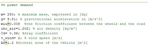
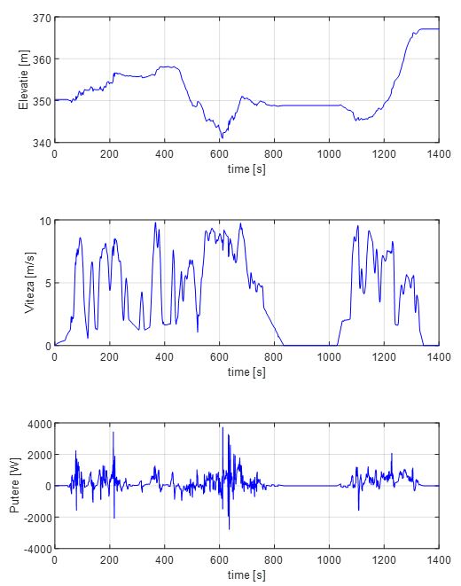
First step is to size the generic capacity of the entire power bank based on vehicle requirements and capacitor parameters. The maximum allowed voltage variation will be used to compute a preliminary capaciy. The power demanded from the electric supply is sized using a Matlab algorithm
Using recorded urban vehicle cycles from Cluj Napoca, the resulting power reaches a maximum of 4kW.
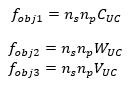
Further on, using optimzation algorithms with objective functions such as costs, weight and volume, the number of series and parallel cells is determined.
The final result returned by the optimization algorithm reached a solution that was compound of 45 series connected cells in one single parallel raw. |
| Act. 2.2. Task 2.1. Sizing the dual-role converter |
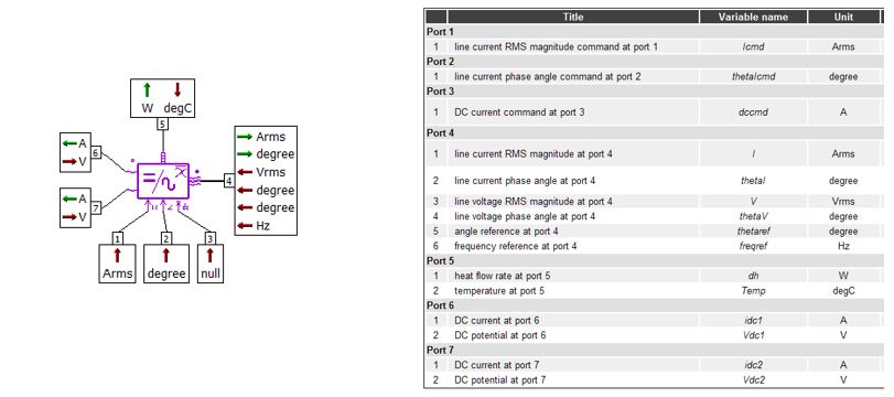
The main components considered when sizing the dual-role power converter were the transistors and the power diodes. In the figure bellow one can see the model of the power converter and its parameters.
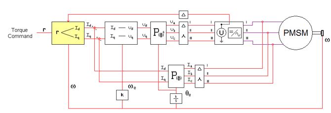
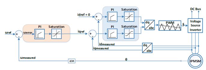
This converter was included in the main control scheme for the motor. Rotor field oriented control method was used as depicted in the figure blow.
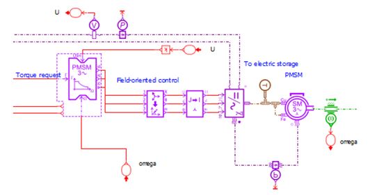
This was implemented in Amesim as depicted in the figure below.
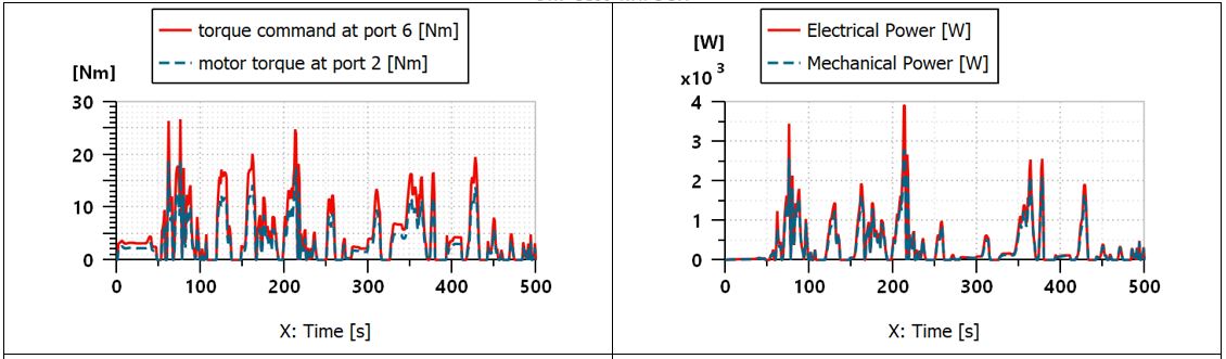
The preliminary results that prove the functionality of the field oriented control and of the power converter is depicted in the plots below. It can be observed that the results follow closely the referances.
|
| Act. 2.3. Task 2.3. The cell voltage equalizer |
Amesim software contains predefined algorithms that allow users to reach satisfactory equalized cell voltages. The concept is to choose corectly between the cell voltage and desired algorithm as depicted below.
|
| Act. 2.4. Task 3.1. Testing the mechanical assemblies via simulatons |
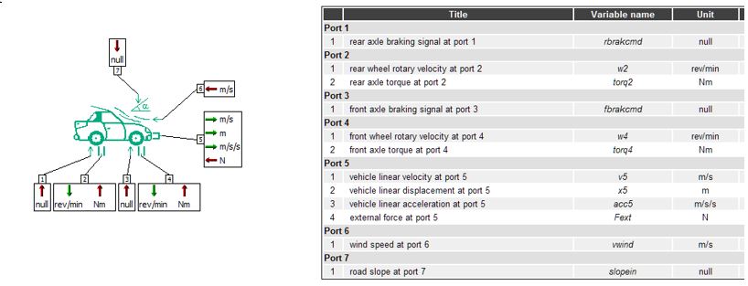
The first element to model is the vehicle chassis. The necesary paramenters for this model were implemented in Amesim software as depicted below.
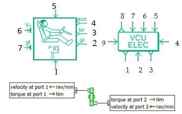
The vehicle model includes the driver, the VCU and the gearbox. All were set in accordance with the specifications of the designed model. These assemblies are depicted below. |
| Act. 2.4. Task 3.2. Simulation of the super-capacitors in Amesim |
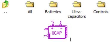
The simulation models for the supercapacitors are to be found in the Electric library of the software as depicted below.
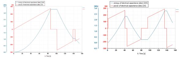
Using the data for the supercapacitors, developed in the previous sections, simulations were performed in order to prove the functionality of the system. Voltage function of the current variations prove the fast dynamics of the supercapacitors.
|
| Act. 2.5. Task 3.2. Simulation of the ultra-capacitors |
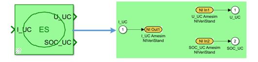
This action was performed using the link between Matlab Simulink and Amesim. The latter was running the ultra-capacitor model while Simulink was running all the rest of the electrical assemblies. It is important to mention that the simulation was running on the real-time PXI computer. The link was created via the ultra-capacitors block that is modelled as an electrical source.
The results obtained prove that the model created in Amesim for the super-capacitors is operational and responds correctly.
|
| Act. 2.6. Task 3.3. Simulation of the PMSM model |
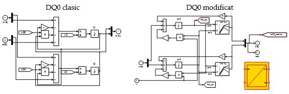
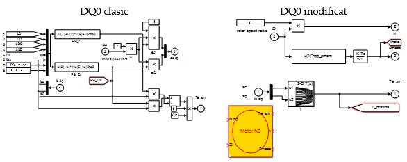
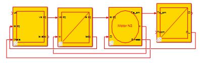
The PMSM model is organized in EMR in order to respect the grant agreement. To reach the multilevel concept, there were built 2 models, one based on LUTs for the inductance variation:
and another one classical approach:
The general model for the PMSM is depicted like:
|
| Act. 2.7. Task 3.. Simulation of the power electronics |
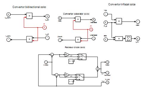
For the power electronics, there were created several approaches in order to reach the required complexity. In doing so, there were built models for the 3 phase inverters as for the DC DC ones. The latter ones must be bidirectional in order to recuperate energy when the EV is breaking. |
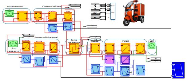
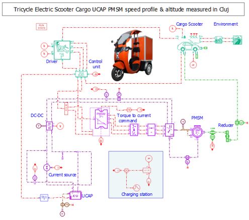
Complete system testing The team created a complete simulation program that contained all the models of each assemblies, including the charger and the vehicle mechanics
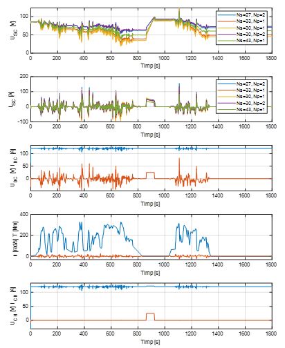
This is depicted in the picture above. A scpecific scenario recorded in Cluj Napoca for 1800s was simulated for all the possible UC combinations, reaching out for good results as it can be seen below
|
Act 3.1 - Task 3.5 Implementarea unitatii de control electronic (ECU) |
The PMSM was controlled using Field Oriented Control (FOC) Strategy described in the figure below
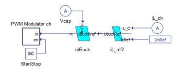
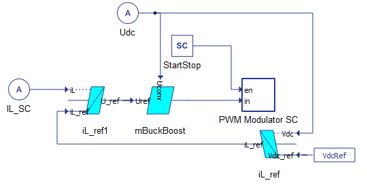
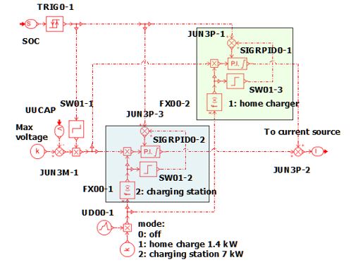
The voltage control loop and the charging station's control loop are detailed in the figures below. It can be seen that these are connected to PWM modulators that ensure the switching signals to the transistors.
The complete vehicle dynamics are implemented in Amesim software. Here, in order to have a comprehensive study, the toque reference must be post processed after measurement, becoming reference for the model.
|
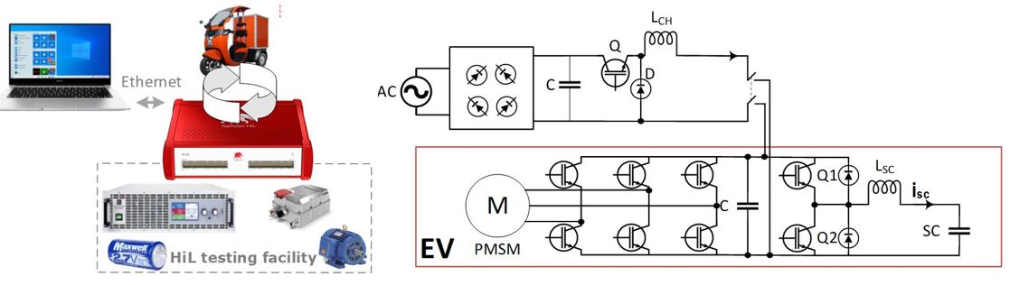
Act 3.2 - Task 4.1 Setting up the HIL test bench |
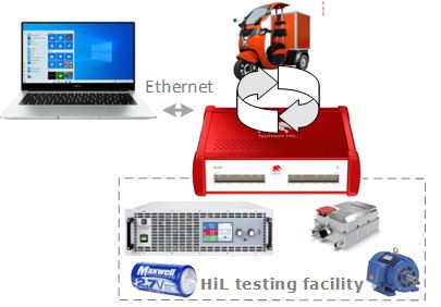
The HIL test bench configuration is detailed in the picture below:
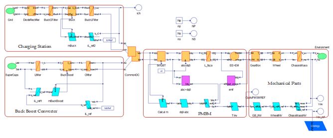
The complete simulation/testing program is depicted in the figure below. One can observe that the EMR concept is used for the model organization.
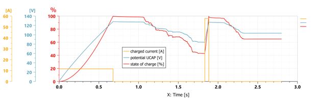
The charging method for the supercapacitors is analized using a program created in Amesim software:
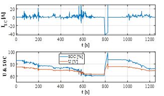
and the results of the charging process are detailed below. It can be observed the SOC, the voltage and the currents variation:
|
Act 3.3 - Task 4.2 The model scalling process |
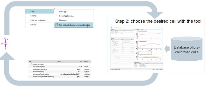
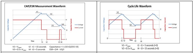
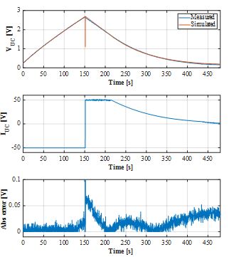
Because the cosnidered vehicle does not need a scaling process, this topic was replaced with the identification and accurate modelling of the supercapacitors. For this, using a real cell the supercapacitors were identified and the new model was tested for accuracy.
It can be seen that the maximum error between measured and simulated results is less than 0.05V. |
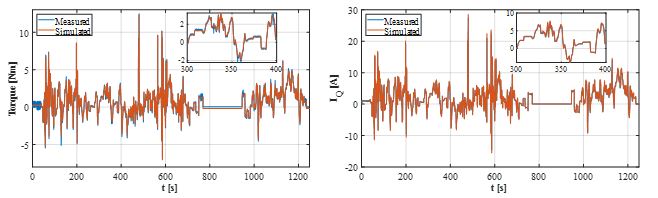
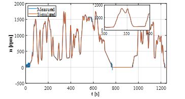
Act 3.4 - Task 4.3 Final HIL testing of the complete system |
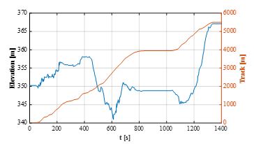
Preliminary the considered recorded urban track from Cluj Napoca was implemented as look up table, referencing the system.
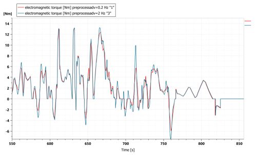
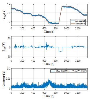
Then the motor results were compared to the simulated outcomes
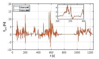
The agreement is noticeable and one can tell that the simulation model is highly accurate compared to measured results. Then, the DC link current was compared between measured and simulated data.
and finally, the supercapacitors behaviour was tested, proving that the vehicle is able to be charged from such a unit supply.
|
The INHERIT project was dedicated to an extensive study to prove that, for an urban electric vehicle, aimed at the utilitarian services of transporting goods over a relatively short distance, the power supply can be made from supercapacitors. The latter will replace classic batteries by eliminating a number of problems such as charging time and life cycles, which supercapacitors are clearly superior to batteries. The downside is that supercapacitors discharge much faster than batteries. However, since it is possible to charge them from the public network in just a few minutes, during which the utility vehicle is parked, loaded or unloaded, this situation is no longer a problem. The project has developed a system for correct sizing and simulation of the entire system of such a vehicle, proving both through simulation and experimental measurements the correct functionality and ease of such an approach.
|